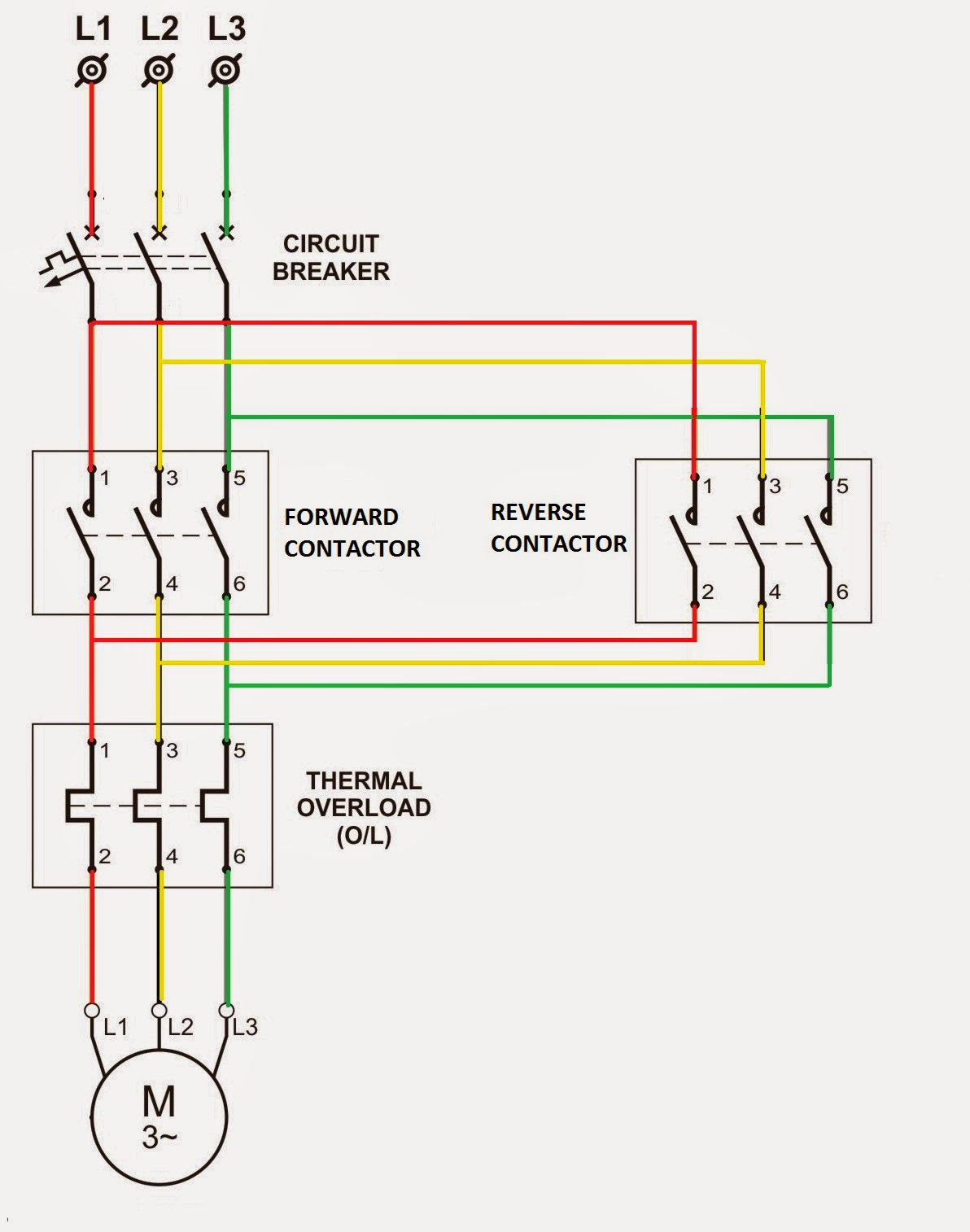
Forward Reverse Relay Circuit Diagram
Figure 2-45.--schematic wiring diagram of an ac reverse-power relay. Reverse motor diagram forward phase control wiring contactor electrical circuit starter three basic relay wire contactors magnetic electric controlling online Reverse timer wiring phase schematic motors
Figure 2-45.--Schematic wiring diagram of an ac reverse-power relay.
Forward reverse contactor wiring Reverse power relay t2000 for generator protection Relay diagram wiring contactor reverse phase overload stop circuit start forward motor ac power starter wire direct dol control magnetic
T2000 relay reverse power protection selco generator circuit control relays
Electrical standards: overload relay working principle and features ofHomebuilt rovs Limit switches motor two circuit reverse dpdt forward relays wire dc control direction relay add using hook down course gifRelays circuit reversing 12v arduino switches timer circuits lift controlling motion.
Su_chef slicesFigure 3-113. reverse power relay test circuit Power reverse relay circuit test tm figure 35c2 force army air.


Electrical Standards: Overload relay working principle and features of

Homebuilt Rovs

Figure 2-45.--Schematic wiring diagram of an ac reverse-power relay.

Figure 3-113. Reverse Power Relay Test Circuit

Reverse Power Relay T2000 for Generator Protection

su_chef slices | bonkerfield

Forward Reverse Contactor Wiring | Electrical Wiring